So last week, I talked about Plates, Switches, and Keycaps which means we are ready to talk about how keyboards detect keypresses. I am hand wiring keyboard so we don’t have a fancy PCB or breadboard in which to solder the pins of our keys. We have to build this key press detection system ourselves. It turns out that we need to build something called a key matrix.
Building the Matrix
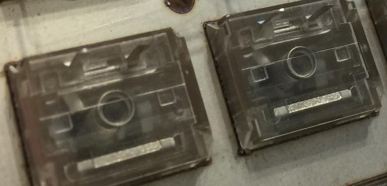
On the bottom of every key switch are two pins, as shown below, that are connected when the switch is depressed.
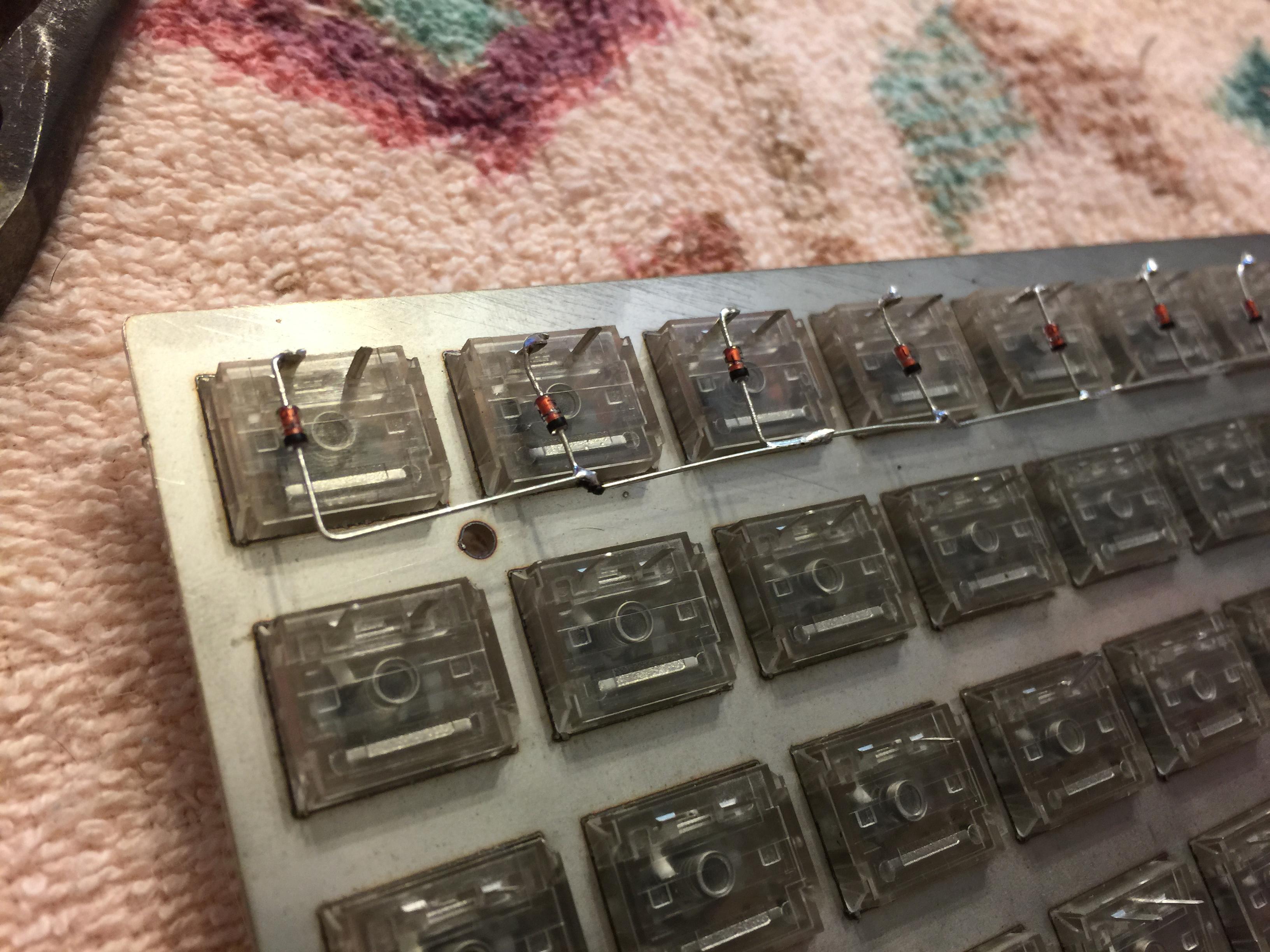
To begin making our matrix, we pick a pin and make a connected row across the bottom of our top line of switches. It is important to use the same side pin on each key switch to make it possible to spot and fix mistakes. If you are wicked smart feel free to mix and match. Now we are gonna make our rows out of little diodes. (I’ll explain why in a few.) Diodes allow current to flow in a single direction, so we have to make sure to put them on “facing” the right way. Since current will be coming from the column side, we face the cathode towards the row. The cathode is indicated by a black ring on our diodes. (We are using 1N4148 diodes.) Here is an example. BTW feel free to laugh at my work I had never done any of this before.
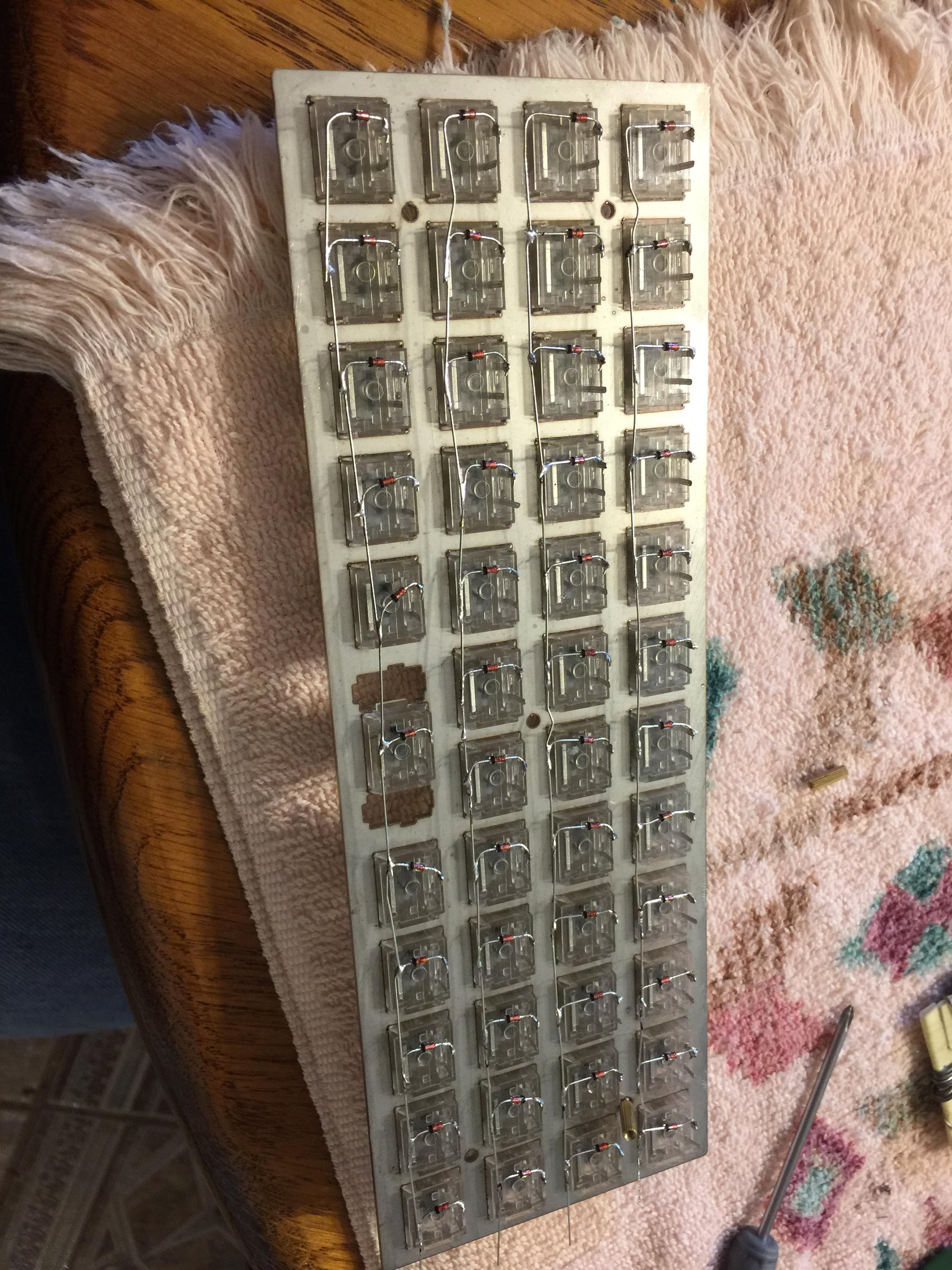
We repeat this for all four rows of the board.
With the rows done, I began working on the columns. For the columns, we run a cable vertically to the second pin. However, we have to make sure that the wires are shielded from the rows. If we don’t, we will have a short in our matrix. Well, if there is a short it no longer is a proper matrix, but anyway back to the important stuff. I used an Exacto blade, and made a circular cut around a stretch of wire at the position of the row 2 switch’s pin. Then using my fingernails, I made a small gap in the insulation of the wire. I repeated this process for the row 3 switch in that same column, and followed with row 1 then row 4. The result is a wire with uninsulated sections at each pin and insulated in between. There is probably an easier way…
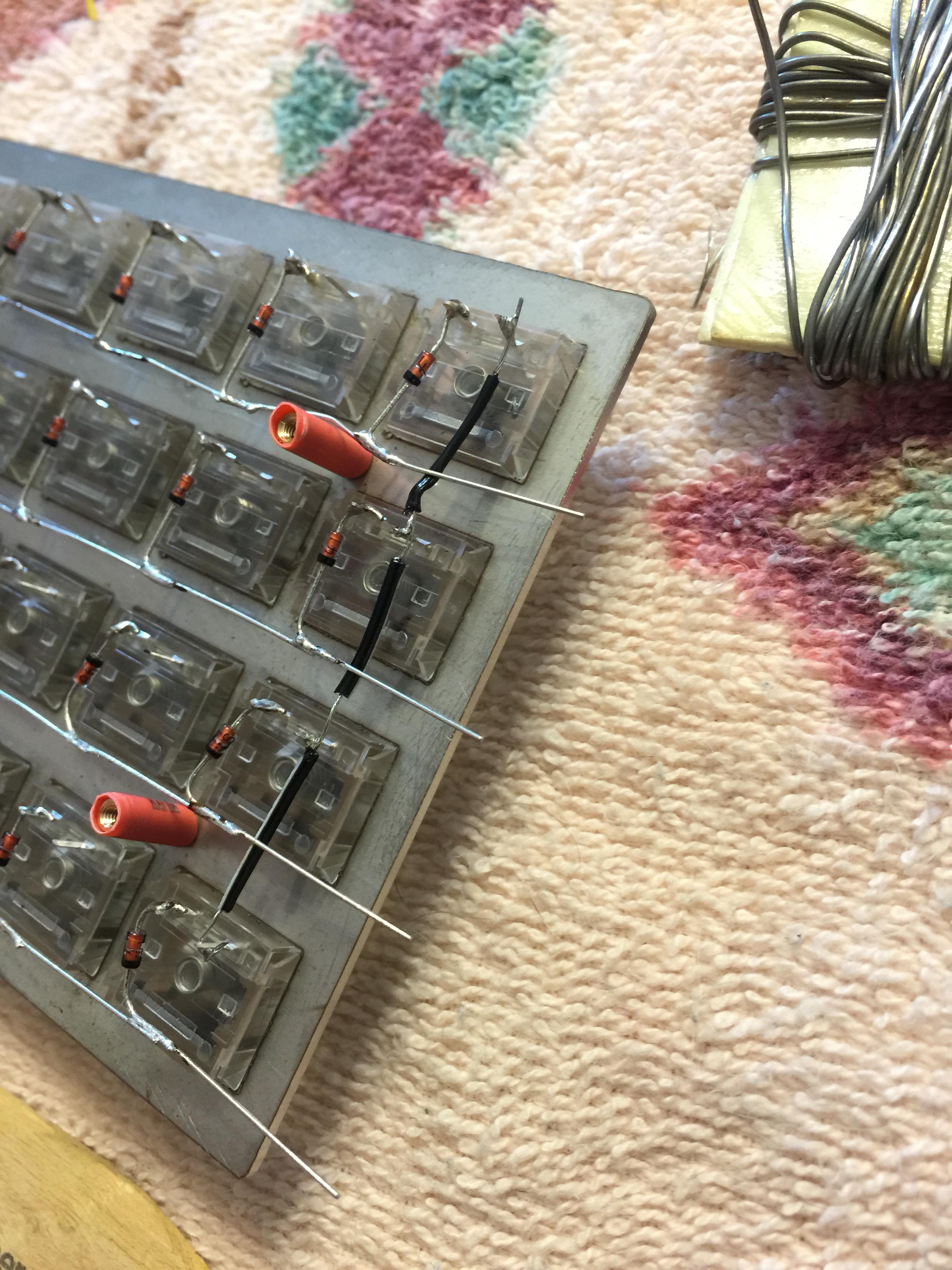
So you repeat that process for every column. There are special cases for wider switches. For example, this board has a two column wide space bar. In that case you wire the space to the which ever column is closet. It is super important to remember which one! Here is an example.
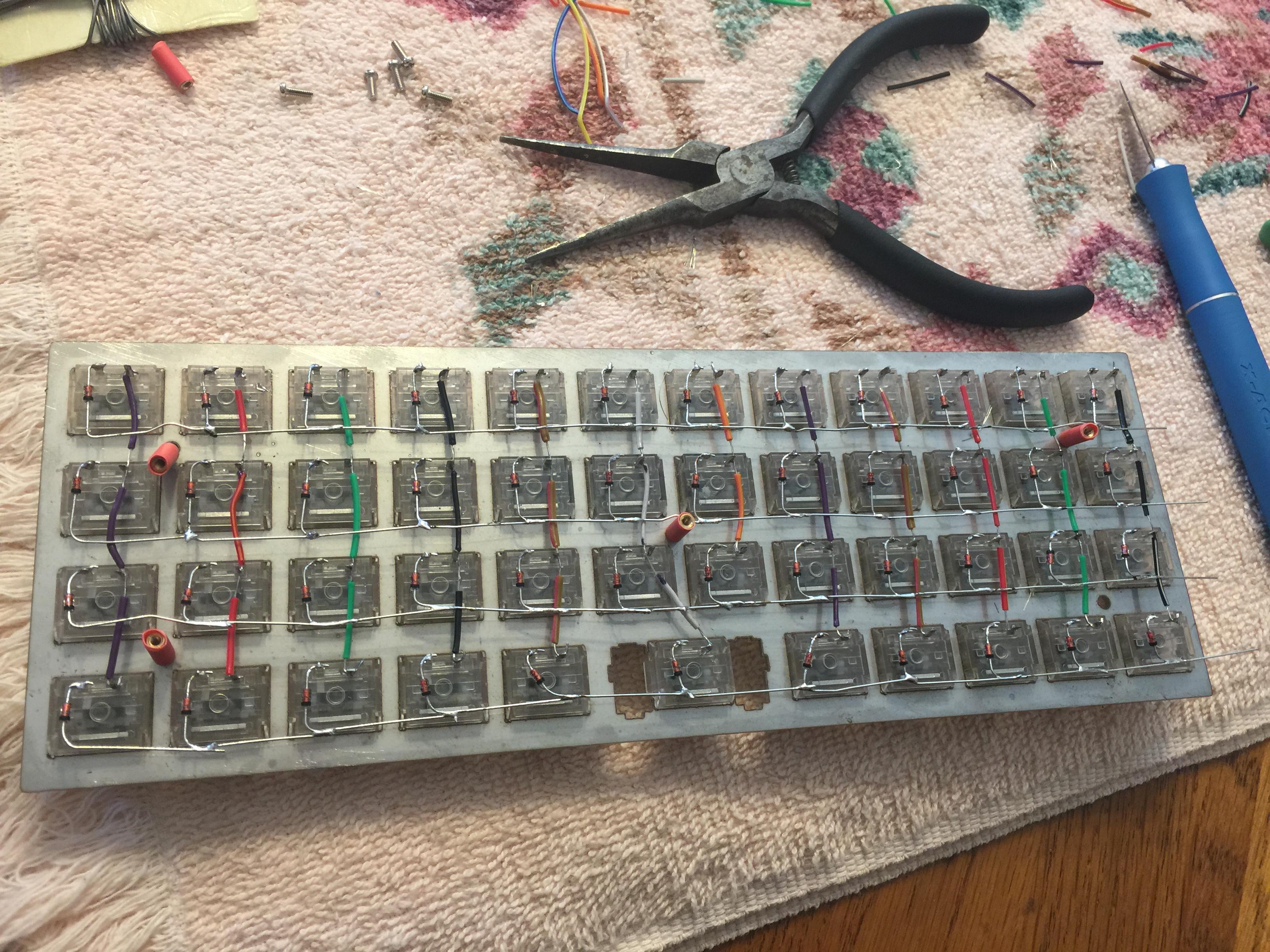
I ran my columns under my rows because their is so little space in the case.
We now have the matrix done!
How the Matrix Works
The matrix works by cycling power through the columns one at a time, and listening to the rows to see what point in the matrix is connected via a key press. So in this image from PCBHeaven.com, we power up the B column while the bottom at the intersection of column B and row 3 is pressed. This sends current to row 3, and we would be able to tell that key B3 was pushed.
This works fine even for multiple keys at once until we have three keys pressed down at once where two of the three are in the same row and two of the three are in the same column. For example if we look at the last image, what if B3, B2, and C2 were all pressed? When column C is powered, we will see C2 as pressed; however, B2 won’t be seen. Also because B2 is pressed the B column has power. This power is connected to row 3 by B3 being pressed, but since we originally powered C, the current on row 3 is interpreted as C3! This problem is known as ghosting. There is another related problem called masking. This occurs when we can not read a change because of ghosting.
To fix these problems, we use a diode on each key. In the scenario above, the B column would not get power from B2 because the diode would prevent it from flowing in that direction. So B3 would not have power, and not be seen while the C column is powered and being read.
Check out pcbheaven for more on this with great animations.
Reading the Matrix
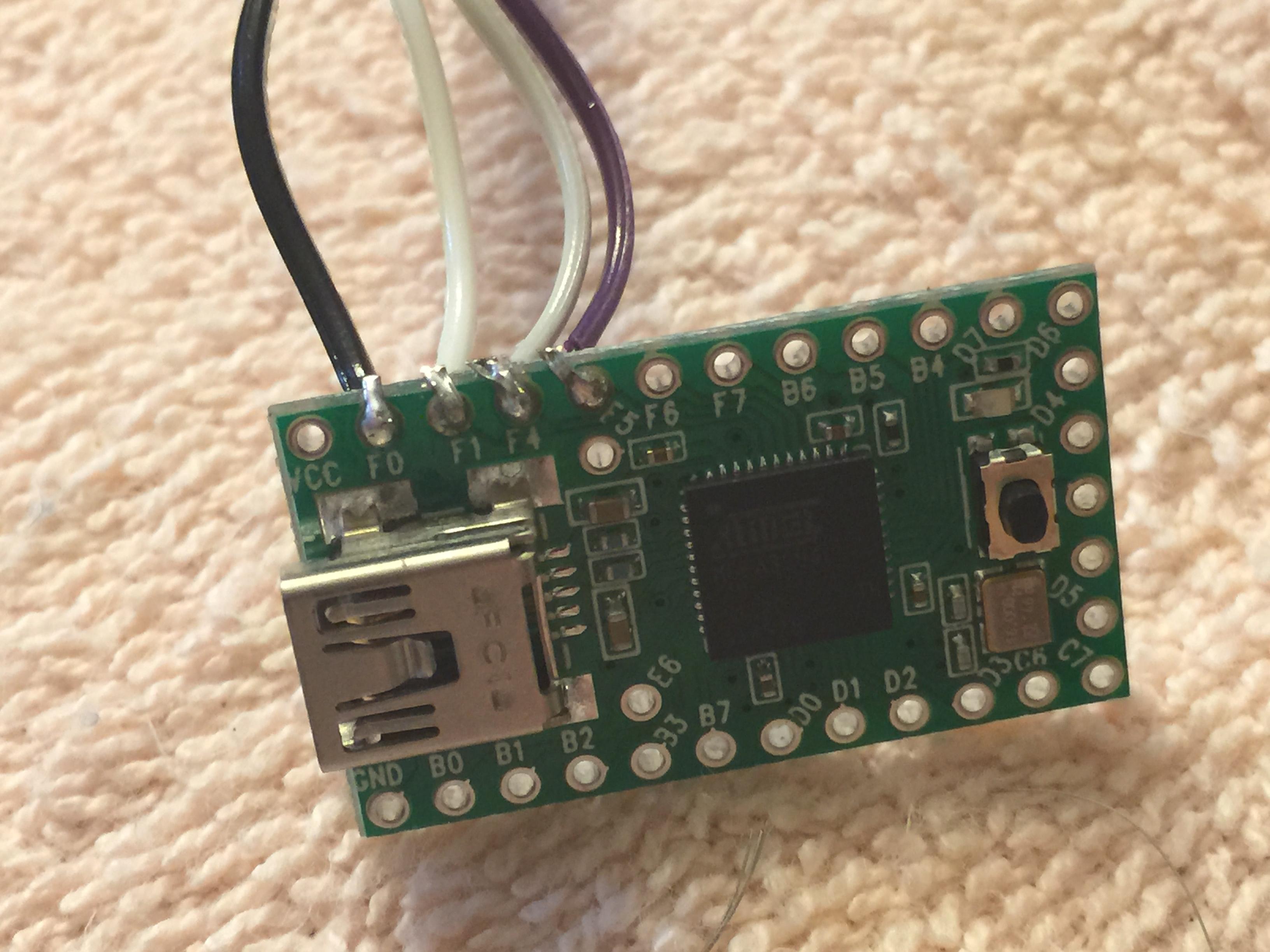
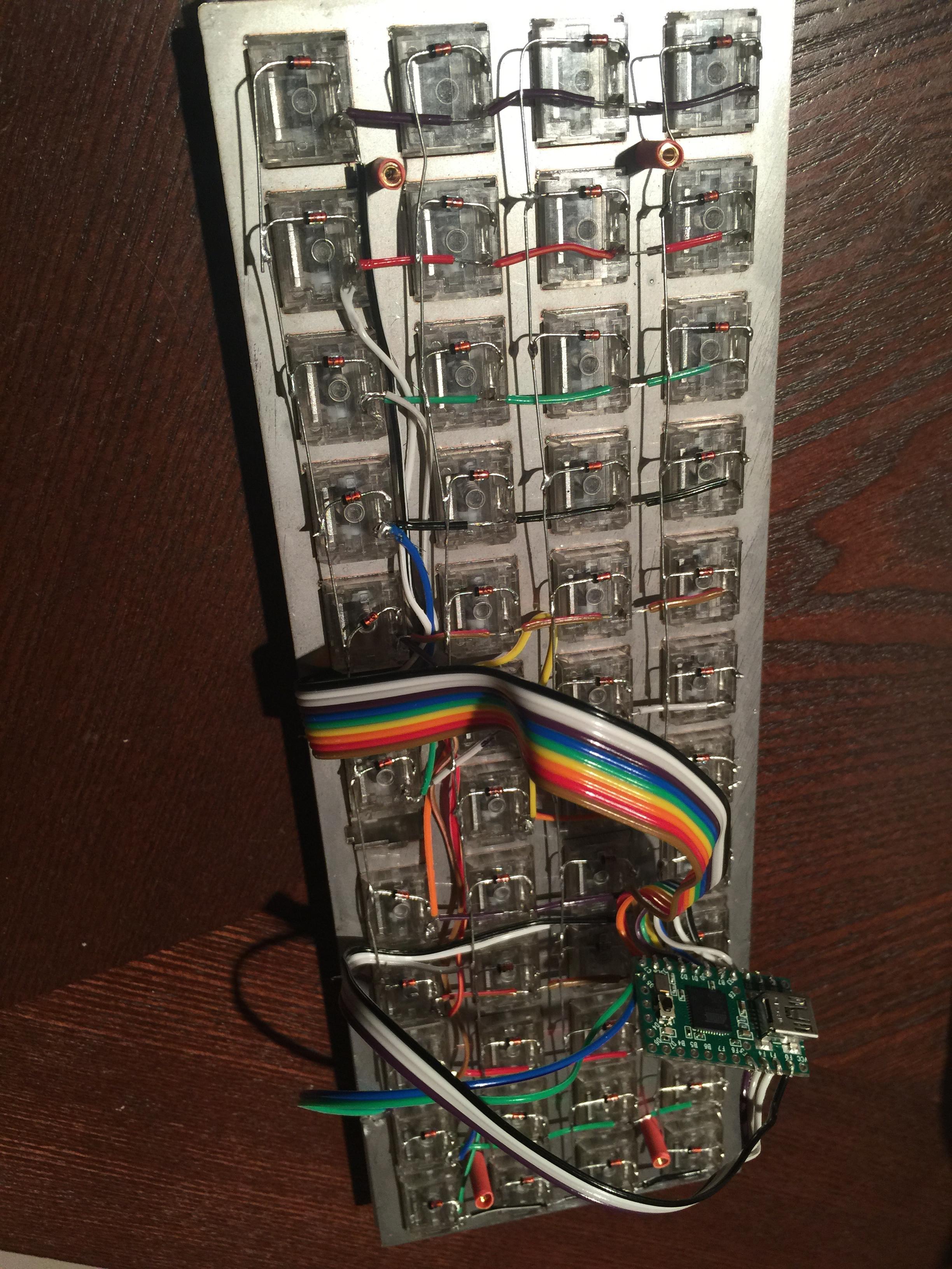
We are going to use a teensy microcontroller as our keyboards brain. We need to connect each row and column to it. I start by connecting some bridge wires to each of them. The teensy will need it’s USB port between columns 2 and 3. so keep that in mind when cabling. I again ran my cables under the row and column cabling.

In that picture, there is a bundle of four cables connected to the rows. I connect those to the teensy first like:
| Teensy PIN | Matrix |
|---|---|
| F0 | row 0 |
| F1 | row 1 |
| F4 | row 2 |
| F5 | row 3 |
Any pin works except for Vcc, GND, RST. Just make note of what went where. I used the upper right corner as row 0, column 0.
Now for the columns. I started on the other side of the teensy as follows:
| Teensy PIN | Matrix |
|---|---|
| D5 | col 0 |
| C7 | col 1 |
| C6 | col 2 |
| D3 | col 3 |
| D2 | col 4 |
| D1 | col 5 |
| D0 | col 6 |
| B7 | col 7 |
| B3 | col 8 |
| B2 | col 9 |
| B1 | col 10 |
| B0 | col 11 |
In the next part we’ll talk about how to program our microcontroller, the teensy, with C. Part 3 will be all keyboard layouts and then it’s about that C, and how we build the firmware for our device.